
On this page
- 1. Preparation: Essential Tools & Safety Guidelines for Alienware M15 R3
- 🎮 Preparing for Your Alienware Adventure
- 🛠️ Specialized Gaming Laptop Tools
- ⚠️ Critical Gaming Laptop Safety
- 💻 Professional Workspace Setup
- 🎒 Recommended Tool Kits for Gaming Laptops
- 👽 Alienware M15 R3 Specific Notes
- ⏱️ Realistic Time Investment
- 🚫 Common Gaming Laptop Mistakes
- ✅ Pre-Repair Verification Checklist
- 🆘 Emergency Preparedness
- 🎯 Ready to Begin Disassembly?
- 2. Initial Disassembly: Bottom Cover & Access Panels for Alienware M15 R3
- 🔧 Entering the Alienware Chassis
- 🔩 Alienware Screw Identification & Mapping
- 🔧 Step-by-Step Gaming Laptop Disassembly
- 👽 Alienware M15 R3 Specific Design
- 🚧 Common Gaming Laptop Challenges
- 🔍 Internal Component Access Points
- 🛡️ Gaming Laptop Damage Prevention
- 📋 Professional Documentation
- 🔍 Troubleshooting Common Issues
- ⏱️ Time Expectations
- 🎉 Success Milestone Achieved!
- 🎯 Ready for Power Safety?
- 3. Battery Removal & Power Safety Procedures for Alienware M15 R3
- ⚠️ CRITICAL SAFETY WARNING
- 🔋 Complete Power Down Sequence
- 📊 Alienware M15 R3 Battery Specifications
- 🔧 Step-by-Step Battery Removal
- 🛡️ Advanced Safety Protocols
- 🚫 Critical Mistakes to Avoid
- 🔌 Battery Connector Technical Details
- ✅ Post-Removal Verification
- 🔄 Genuine Replacement Battery Information
- 🆘 Emergency Response Procedures
- ⏱️ Time Expectations
- 🎯 Ready for Cooling System Work?
- 4. Cooling System Disassembly & Thermal Management for Alienware M15 R3
- ❄️ Alienware Cryo-Tech Cooling System Overview
- 📊 Cooling System Technical Specifications
- 🛠️ Pre-Disassembly Preparation
- 🔧 Step-by-Step Cooling System Disassembly
- 🔥 Thermal Interface Material Management
- 📏 Thermal Pad Thickness Guide
- 🎨 Professional Thermal Paste Application
- ⚙️ Cooling System Reassembly Procedure
- 📈 Post-Service Performance Verification
- 🔍 Common Cooling Issues & Solutions
- 🚀 Cooling System Upgrade Opportunities
- 📅 Recommended Maintenance Schedule
- 🎯 Ready for Memory Upgrades?
- 5. Memory Installation & RAM Upgrade Options for Alienware M15 R3
- 🚀 Why Upgrade Your Alienware M15 R3 Memory?
- 📊 Alienware M15 R3 Memory Specifications
- 🔍 Memory Compatibility Verification
- ⚙️ Recommended Memory Configurations
- 🛠️ Pre-Installation Preparation
- 🔧 Step-by-Step Memory Installation
- ⚡ Dual-Channel Memory Benefits
- 📈 Memory Speed Performance Comparison
- ✅ Post-Installation Verification
- 🔍 Troubleshooting Common Memory Issues
- 🏆 Recommended Memory Kits for Alienware M15 R3
- 📊 Real-World Gaming Performance Impact
- 🔮 Future-Proofing Your Memory Upgrade
- 🎯 Ready for Storage Upgrades?
- 6. Storage Solutions: SSD & M.2 Installation for Alienware M15 R3
- ⚡ Transform Your Gaming Experience with SSD Upgrades
- 📊 Alienware M15 R3 Storage Specifications
- 🔍 SSD Compatibility & Selection Guide
- 💾 Recommended Storage Configurations
- 🛠️ Pre-Installation Preparation
- 🔧 Step-by-Step SSD Installation
- 🚀 RAID 0 Performance Configuration
- 📈 Storage Performance Comparison
- 🔄 Data Migration & Cloning Options
- 🎯 Post-Installation Optimization
- 🔍 Troubleshooting Common SSD Issues
- 🏆 Recommended SSD Models for Alienware M15 R3
- 🎮 Real-World Gaming Performance Impact
- 📊 Storage Capacity Planning Guide
- 🎯 Ready for Advanced Repairs?
- 7. Motherboard Access & Component-Level Repair for Alienware M15 R3
- ⚠️ ADVANCED REPAIR WARNING
- 📊 Alienware M15 R3 Motherboard Specifications
- 🔧 Advanced Repair Equipment Required
- 🔧 Complete Disassembly Sequence for Motherboard Access
- 🗺️ Motherboard Connector Identification Map
- 🔍 Common Motherboard Issues & Diagnostics
- 🔌 Component-Level Repair Procedures
- 🚫 BGA COMPONENT WARNING
- 🔬 Advanced Diagnostic Techniques
- 📊 Repair Difficulty Assessment
- 🔋 Professional Soldering Techniques
- ✅ Post-Repair Testing Procedures
- 🔍 Replacement Parts Sourcing
- 💰 Repair vs Replacement Cost Analysis
- 🎯 Ready for Keyboard & Display Work?
- 8. Keyboard & Top Case Assembly Removal for Alienware M15 R3
- ⚠️ DELICATE COMPONENT WARNING
- 📊 Alienware M15 R3 Keyboard Specifications
- 🔧 Specialized Tools Required
- 🛠️ Pre-Removal Preparation Steps
- 🔧 Step-by-Step Keyboard Removal
- 🔩 Top Case Assembly Removal
- 🔌 Ribbon Cable Handling Guide
- 🔍 Common Issues & Solutions
- 🌈 AlienFX RGB Lighting System
- ⚙️ Professional Reassembly Techniques
- ✅ Post-Reassembly Testing
- 🔧 Replacement Parts Information
- ⏱️ Time Investment Estimates
- 🎯 Ready for Display Work?
- 9. Display Assembly & Screen Replacement Guide for Alienware M15 R3
- ⚠️ HIGH-RISK COMPONENT WARNING
- 📊 Alienware M15 R3 Display Specifications
- 🔍 Screen Compatibility Verification
- 🔧 Specialized Display Tools Required
- 🛠️ Pre-Removal Preparation
- 🔧 Step-by-Step Display Removal
- 🔌 Display Cable Identification Guide
- 🔄 New Screen Preparation
- ⚙️ Screen Installation Procedure
- 🔩 Hinge Maintenance & Replacement
- ✅ Post-Installation Testing
- 🔍 Troubleshooting Common Issues
- 🔧 Replacement Parts Sourcing
- 🚀 Display Upgrade Considerations
- ⏱️ Time Investment Estimates
- 🎯 Ready for Reassembly?
- 10. Where to Sell Your Upgraded Alienware M15 R3: Maximize Your Return
- 💰 Unlock Your Alienware's True Value
- 🔧 Pre-Sale Preparation Checklist
- 🏛️ Government & Education Buyback Programs
- 💻 Specialized Laptop Buyback Services
- 🛒 Direct-to-Consumer Platforms
- 🎮 Gaming-Specific Marketplaces
- 💵 Smart Pricing Strategy
- 📈 Listing Optimization Tips
- 🛡️ Payment & Security Best Practices
- 📊 Tax & Legal Considerations
- 📅 Best Times to Sell
- 🔄 Alternative Options
- 🎯 Recommended Selling Strategy
- Need to Sell Your Alienware Laptop? Get Instant Cash!
1. Preparation: Essential Tools & Safety Guidelines for Alienware M15 R3
🎮 Preparing for Your Alienware Adventure
Disassembling a gaming laptop like the Alienware M15 R3 requires specific tools and careful preparation. This premium gaming machine has unique construction that demands the right approach from the very beginning.
🛠️ Specialized Gaming Laptop Tools
- Essential Screwdrivers:
- Torx T5 (for most external and structural screws)
- Torx T6 (for heatsink and motherboard mounts)
- Phillips #00 (for smaller internal components)
- Phillips #0 (for larger brackets and shields)
- Magnetic tips strongly recommended
- Gaming Laptop Specific Tools:
- Plastic spudger set (essential for clip-heavy chassis)
- Nylon opening tools for delicate gaming components
- Suction cups for display handling
- Anti-static wrist strap (critical for GPU components)
- iFixit Pro Tech Toolkit recommended
⚠️ Critical Gaming Laptop Safety
- Complete Power Down:
- Use Windows shutdown menu for proper system closure
- Unplug 240W gaming power adapter
- Disconnect all gaming peripherals and accessories
- Hold power button for 15 seconds to discharge capacitors
- Verify all Alienware lighting is completely off
- Static Protection:
- Use ESD wrist strap throughout entire process
- Work on anti-static mat or non-carpeted surface
- Avoid synthetic clothing that generates static
- Ground yourself before handling any components
- Component Handling:
- Never force components - gaming laptops have tight tolerances
- Handle GPU and CPU with extreme care
- Keep magnets away from storage and memory
- Use plastic tools only around sensitive components
💻 Professional Workspace Setup
- Ideal Gaming Laptop Workspace:
- Clean, large surface with anti-static protection
- Excellent lighting from multiple angles
- Magnetic project mat for screw organization
- Multiple small containers for different screw types
- Soft cloth or padding for display protection
- Organization System:
- Label screws by component and location
- Take photos at every step with your phone
- Keep track of screw lengths and types
- Document cable routing patterns
🎒 Recommended Tool Kits for Gaming Laptops
| Kit Type | Tools Included | Price Range | Best For | Alienware Compatibility |
|---|---|---|---|---|
| Professional Gaming Kit | Full Torx set, spudgers, tweezers, ESD protection | $60-100 | Regular gaming laptop repairs | Excellent |
| Essential Electronics Kit | Basic Torx, Phillips, plastic tools | $30-50 | Occasional upgrades | Good |
| Budget Starter Set | Basic screwdrivers, minimal accessories | $15-25 | Single repairs only | Fair |
👽 Alienware M15 R3 Specific Notes
- Unique Design Features:
- Premium build quality with tight tolerances
- Advanced cooling system with vapor chamber
- Dedicated GPU with complex mounting
- Alienware Command Center integration
- Customizable RGB lighting systems
- Special Considerations:
- More screws than typical laptops
- Complex clip system around perimeter
- Delicate ribbon cables for lighting
- Thermal management critical for performance
⏱️ Realistic Time Investment
| Repair Type | Beginner Time | Experienced Time | Complexity Level |
|---|---|---|---|
| RAM/SSD Upgrade | 30-45 minutes | 15-20 minutes | ⭐️⭐️⭐️ |
| Battery Replacement | 45-60 minutes | 20-30 minutes | ⭐️⭐️⭐️⭐️ |
| Thermal System Service | 60-90 minutes | 30-45 minutes | ⭐️⭐️⭐️⭐️⭐️ |
| Motherboard Access | 90-120 minutes | 45-60 minutes | ⭐️⭐️⭐️⭐️⭐️ |
🚫 Common Gaming Laptop Mistakes
- Forceful Disassembly:
- Alienware clips require finesse, not force
- If something resists, check for missed screws
- Never use metal tools for prying
- Static Damage:
- GPU and CPU are extremely static-sensitive
- Always use proper ESD protection
- Handle components by edges only
- Poor Organization:
- Mixing screw types leads to reassembly issues
- Take photos of every step
- Keep components separated and labeled
✅ Pre-Repair Verification Checklist
- ✅ All necessary tools gathered and organized
- ✅ Workspace cleared and properly set up
- ✅ Laptop completely powered down and unplugged
- ✅ ESD protection equipment ready and tested
- ✅ Camera/phone charged for documentation
- ✅ Adequate time allocated for the repair
- ✅ Emergency contacts noted if help needed
🆘 Emergency Preparedness
- When to Stop:
- If you encounter unexpected resistance
- When components don't match expected layout
- If you feel unsure or uncomfortable
- When working beyond your skill level
- Help Resources:
- Dell Alienware Support
- Alienware user communities and forums
- Local computer repair specialists
- Online gaming laptop repair communities
2. Initial Disassembly: Bottom Cover & Access Panels for Alienware M15 R3
🔧 Entering the Alienware Chassis
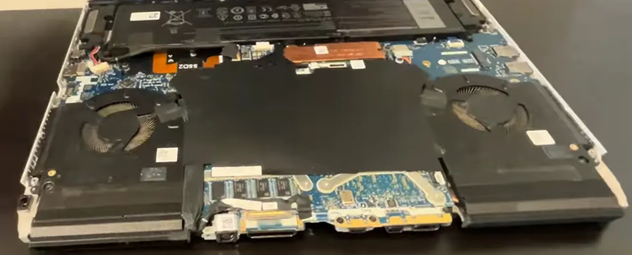
The Alienware M15 R3 features a sophisticated chassis design with multiple access points and a complex clip system. This initial disassembly requires patience and precision to avoid damaging the premium gaming construction.
🔩 Alienware Screw Identification & Mapping
| Screw Location | Type | Quantity | Length | Gaming Laptop Notes |
|---|---|---|---|---|
| Perimeter Short Screws | Torx T5 | 8 | 4mm | Standard length, around edges |
| Central Long Screws | Torx T5 | 6 | 6mm | Near cooling system and structural points |
| Access Panel Screws | Torx T5 | 4 | 5mm | Easy-access upgrade compartment |
| Warranty Stickers | N/A | 2 | N/A | Check Alienware Warranty Status |
🔧 Step-by-Step Gaming Laptop Disassembly
- Access Panel Removal (Easiest First):
- Locate the dedicated upgrade access panel
- Remove 4 Torx T5 screws securing the panel
- Lift panel straight up - no clips to release
- This gives immediate access to RAM and primary SSD
- Perfect for quick memory or storage upgrades
- Main Bottom Cover Screw Removal:
- Remove all 14 Torx T5 screws in star pattern
- Start from corners and work toward center
- Use magnetic screwdriver to prevent loss
- Note different screw lengths for reassembly
- Keep screws organized by location on magnetic mat
- Gaming Laptop Clip Release Technique:
- Start at rear corners near exhaust vents
- Insert plastic pry tool at 20-degree angle
- Gently twist to release first clips (listen for soft clicks)
- Work around perimeter, releasing clips every 2 inches
- Use guitar picks for better leverage on stubborn clips
- Alternate sides to prevent chassis warping
- Professional Cover Separation:
- Lift from rear edge first (near ports)
- Angle upward at 15 degrees to clear internal components
- Check for any missed clips or hidden screws
- Set cover aside on clean, static-free surface
- Note internal cable routing for reassembly
👽 Alienware M15 R3 Specific Design
- Premium Construction Elements:
- Magnesium alloy frame with copper cooling
- Advanced thermal management system
- Dedicated GPU with vapor chamber cooling
- Multiple cooling fans with independent control
- Alienware Command Center integration
- Internal Layout Overview:
- Dual DDR4 SODIMM slots (up to 32GB)
- Dual M.2 2280 NVMe storage slots
- NVIDIA RTX graphics card (dedicated)
- Killer Wi-Fi 6 AX1650 card
- 90Whr battery with advanced power management
🚧 Common Gaming Laptop Challenges
- Stubborn Gaming Laptop Clips:
- Apply gentle heat with hairdryer (low setting, 3-5 seconds)
- Use plastic business cards for better leverage
- Alternate sides every 2-3 clips to prevent permanent deformation
- Never force - reposition tool if resistance increases suddenly
- Check for hidden screws or missed retention points
- Stripped Screws in Premium Equipment:
- Use rubber band between screw and driver for enhanced grip
- Try slightly larger Torx bit if available
- As last resort, use screw extraction kit
- Replace damaged screws during reassembly
- Document any damaged hardware for transparency
🔍 Internal Component Access Points
- Immediately Accessible Components:
- Two DDR4 memory slots (easy upgrade)
- Primary M.2 NVMe storage slot
- Wi-Fi 6 card with antenna connections
- Battery connector and mounting points
- Cooling fans and heat pipe assembly
- Requires Further Disassembly:
- Secondary M.2 storage slot
- Dedicated GPU and CPU cooling system
- Keyboard assembly and RGB lighting
- Display assembly and hinge mechanisms
- Motherboard and power delivery system
🛡️ Gaming Laptop Damage Prevention
- Clip Preservation Techniques:
- Work slowly and methodically around entire perimeter
- Use plastic tools only against plastic components
- If clip breaks, note location for reassembly adjustment
- Apply even, consistent pressure to prevent bending
- Document any clip damage for records
- Component Protection:
- Avoid touching motherboard circuitry with metal tools
- Keep screws organized and away from internal components
- Use ESD protection at all times
- Don't force connectors or ribbon cables
- Handle dedicated GPU with extreme care
📋 Professional Documentation
- Essential Photos to Take:
- Screw locations before removal
- Clip condition around perimeter
- Cable routing and connector locations
- Component layout and orientation
- Any pre-existing damage or wear
- Quality Assurance Checklist:
- Verify all 18 screws are properly removed
- Check for hidden retention points or clips
- Ensure no cables are attached to bottom cover
- Confirm clean separation without forced removal
- Document any challenges encountered
🔍 Troubleshooting Common Issues
- Cover Won't Sit Flush After Service:
- Check for missed clips or internal obstructions
- Verify all internal components are properly seated
- Ensure no cables are trapped under cover edges
- Inspect for bent or damaged clip receptacles
- Gaps or Misalignment:
- Check clip alignment around entire perimeter
- Verify all screws are proper length for locations
- Ensure no damage to mating surfaces or guides
- Confirm proper screw tightening sequence
⏱️ Time Expectations
| Experience Level | Estimated Time | Notes |
|---|---|---|
| First Time | 20-30 minutes | Take it slow, be methodical |
| Some Experience | 12-18 minutes | Comfortable with gaming laptop construction |
| Experienced | 6-10 minutes | Familiar with Alienware clip systems |
🎉 Success Milestone Achieved!
- You've Successfully:
- Navigated Alienware's premium chassis design
- Mastered the complex clip release system
- Gained access to critical internal components
- Preserved the gaming laptop's build quality
- Now Accessible for Upgrades:
- RAM installation and memory upgrades
- Primary SSD replacement and upgrades
- Wi-Fi card replacement
- Battery replacement
- Cooling system maintenance
0:30 Bottom case 1:40 Rear Vent Cover 2:20 Battery 4:25 Speakers 4:54 SSD Storage 6:10 WiFi Card 6:45 Right IO Board 8:15 Left IO Board 8:47 Heatsink and Cooling Fans 9:51 Motherboard 9:55 Processor and GPU 10:16 DC Power Jack 10:51 Hinges 11:26 Display Assembly 11:50 Palmrest Assembly 11:57 Keyboard 12:03 Touchpad 12:24 Power Button
3. Battery Removal & Power Safety Procedures for Alienware M15 R3
⚠️ CRITICAL SAFETY WARNING
Battery removal is the MOST DANGEROUS step in Alienware M15 R3 disassembly. The 90Whr lithium-ion battery can cause serious injury, permanent damage to components, or fire if mishandled. Follow these procedures exactly.
🔋 Complete Power Down Sequence
- Proper System Shutdown:
- Save all work and close all applications
- Use Windows Start Menu → Power → Shutdown
- Wait 30 seconds for complete system power down
- Verify all Alienware RGB lighting is completely off
- External Power Disconnection:
- Unplug 240W Alienware power adapter from wall outlet
- Disconnect power adapter from laptop DC-in port
- Remove all USB-C devices and peripherals
- Disconnect external monitors and docking stations
- Capacitor Discharge Procedure:
- Press and hold power button for 15 seconds
- Repeat power button hold 3 times with 5-second intervals
- This discharges residual power in motherboard capacitors
- Verify no lights illuminate during final power button press
📊 Alienware M15 R3 Battery Specifications
| Specification | Details | Safety Notes |
|---|---|---|
| Battery Type | Lithium-Ion Polymer | Extremely flammable if punctured |
| Capacity | 90Whr (6-Cell) | High energy density - handle with care |
| Voltage | 11.4V DC | Can deliver dangerous current |
| Part Number | Dell 9K4N4 / 0K4N4 | Use only genuine Alienware replacements |
| Location | Front-center of chassis | Protected by metal shield |
🔧 Step-by-Step Battery Removal
- Initial Safety Verification:
- Confirm laptop is completely powered down
- Verify power adapter is disconnected
- Wear ESD wrist strap properly grounded
- Work on non-conductive, static-free surface
- Battery Connector Identification:
- Locate white battery connector near center of motherboard
- Identify locking mechanism on connector housing
- Note cable routing under and around other components
- Take photos of connector orientation before disconnection
- Safe Connector Disconnection:
- Use plastic spudger to release connector locking tabs
- Gently rock connector side-to-side (never pull straight up)
- If resistance is felt, verify locking mechanism is fully released
- Once free, carefully move connector away from motherboard
- Battery Mounting Screw Removal:
- Remove 4 Torx T5 screws securing battery to chassis
- Note screw lengths for proper reassembly
- Keep screws organized in labeled container
- Check for any adhesive strips under battery
- Battery Extraction:
- Lift from front edge first (near touchpad)
- Use plastic tools only - no metal near battery
- If adhesive is present, use isopropyl alcohol to release
- Place battery on non-conductive surface immediately
🛡️ Advanced Safety Protocols
- Electrostatic Discharge (ESD) Protection:
- Wear ESD wrist strap connected to grounded surface
- Work on ESD-safe mat or non-conductive surface
- Avoid synthetic clothing that generates static
- Ground yourself before handling any components
- Battery Handling Safety:
- Never puncture or bend lithium-ion batteries
- Keep batteries away from metal objects and tools
- Store removed battery in fire-proof container
- Dispose of damaged batteries properly at certified facilities
- Emergency Procedures:
- Keep Class D fire extinguisher nearby
- Have baking soda available for battery acid spills
- Know emergency shutdown procedures
- Work in well-ventilated area
🚫 Critical Mistakes to Avoid
- Power Sequence Errors:
- Never disconnect battery while system has power
- Avoid working on powered-on or sleeping laptop
- Don't skip capacitor discharge procedure
- Verify complete power down before proceeding
- Physical Damage Risks:
- Never use metal tools near battery connector
- Avoid excessive force on battery connector
- Don't pry battery with sharp objects
- Never stack components on top of battery
- Reassembly Errors:
- Never reassemble without proper battery connection
- Avoid pinching battery cables during reassembly
- Don't overtighten battery mounting screws
- Verify connector is fully seated and locked
🔌 Battery Connector Technical Details
| Pin | Function | Voltage | Safety Notes |
|---|---|---|---|
| 1-2 | Positive (+) Power | 11.4V | HIGH VOLTAGE - exercise extreme caution |
| 3-4 | Negative (-) Ground | 0V | System ground reference |
| 5-6 | Data Communication | 3.3V | Battery management system communication |
| 7-8 | Thermal Sensor | 1.8V | Temperature monitoring and safety |
✅ Post-Removal Verification
- Visual Inspection:
- Check battery for swelling, leaks, or damage
- Inspect connector for bent pins or damage
- Verify no cable damage during removal
- Check motherboard for any signs of short circuits
- Multimeter Verification:
- Set multimeter to DC voltage setting
- Check battery terminals for residual voltage (should be minimal)
- Verify motherboard power rails are discharged
- Document any abnormal readings
- Component Safety Check:
- Ensure battery is stored safely away from work area
- Verify work area is clear of conductive materials
- Confirm ESD protection is still active
- Prepare for next disassembly steps
🔄 Genuine Replacement Battery Information
- OEM Part Numbers:
- Dell 9K4N4 (Primary part number)
- Dell 0K4N4 (Alternative part number)
- Compatible with Alienware M15 R3 only
- Verify compatibility with your specific model
- Genuine vs Third-Party:
- Genuine Dell: Guaranteed compatibility, full warranty
- Premium Third-Party: Good quality, verify reviews
- Budget Options: Risk of poor performance/safety
- Always check Dell Official Parts first
🆘 Emergency Response Procedures
- Battery Damage Response:
- If battery is punctured or leaking: EVACUATE AREA
- Use Class D fire extinguisher for lithium battery fires
- Never use water on lithium battery fires
- Contact professional hazardous materials disposal
- Electrical Shock Response:
- Disconnect all power sources immediately
- Do not touch person experiencing shock
- Call emergency services if shock occurs
- Have first aid kit readily available
⏱️ Time Expectations
| Experience Level | Estimated Time | Safety Level |
|---|---|---|
| First Time | 15-25 minutes | High (if following procedures) |
| Some Experience | 8-12 minutes | Medium-High |
| Experienced | 4-6 minutes | Medium (familiarity risk) |
4. Cooling System Disassembly & Thermal Management for Alienware M15 R3
❄️ Alienware Cryo-Tech Cooling System Overview
The Alienware M15 R3 features an advanced vapor chamber cooling system with dual fans and multiple heat pipes. This premium thermal solution is designed for high-performance gaming but requires careful handling during disassembly to maintain optimal performance.
📊 Cooling System Technical Specifications
| Component | Specification | Performance Impact |
|---|---|---|
| Cooling Type | Vapor Chamber + Heat Pipes | Superior heat dissipation vs traditional heat pipes |
| Heat Pipes | 4x Copper Heat Pipes | Distributes heat across entire cooling assembly |
| Fans | Dual 80mm High-Performance Fans | Independent CPU/GPU control via Alienware Command Center |
| Fin Stack | 124 Copper Fins | Maximizes surface area for heat exchange |
| Thermal Interface | Element 31 Thermal Compound | Gallium-based liquid metal compound (CPU only) |
🛠️ Pre-Disassembly Preparation
- Required Thermal Materials:
- High-quality thermal paste (Arctic MX-4 or Noctua NT-H1)
- Thermal pads (0.5mm, 1.0mm, 1.5mm thicknesses)
- 99% isopropyl alcohol for cleaning
- Lint-free coffee filters or swabs
- Plastic spudgers for safe component removal
- Safety Verification:
- Confirm battery is completely disconnected
- Verify all power sources are removed
- Wear ESD protection throughout process
- Work in clean, well-lit environment
🔧 Step-by-Step Cooling System Disassembly
- Fan Cable Disconnection:
- Locate two fan connectors on motherboard (CPU and GPU fans)
- Use plastic spudger to gently release connector locking tabs
- Note cable routing for proper reassembly
- Carefully move cables away from cooling assembly
- Heatsink Screw Identification:
- Identify 8 spring-loaded heatsink screws (marked with numbers)
- Note screw numbering sequence for proper reassembly tension
- 4 screws for CPU vapor chamber
- 4 screws for GPU heatsink assembly
- All screws are Torx T6 size
- Proper Screw Removal Sequence:
- Follow reverse star pattern for screw removal
- Loosen screws in sequence: 8, 7, 6, 5, 4, 3, 2, 1
- Turn each screw 2-3 rotations before moving to next
- Complete removal only after all screws are loosened
- Heatsink Separation Technique:
- Gently twist heatsink left and right to break thermal compound seal
- Never pry or force heatsink separation
- If resistance is felt, recheck for missed screws
- Lift straight up once thermal interface is broken
- Fan Assembly Removal:
- Remove 2 Torx T5 screws securing each fan assembly
- Lift fans straight up from mounting points
- Note fan orientation and cable routing paths
- Clean fan blades with compressed air if necessary
🔥 Thermal Interface Material Management
⚠️ CRITICAL WARNING: LIQUID METAL HANDLING
The Alienware M15 R3 uses Element 31 gallium-based thermal compound on the CPU. This conductive material can short-circuit and destroy components if mishandled.
- Safe Liquid Metal Containment:
- Inspect for any liquid metal leakage outside CPU die
- Use cotton swabs with isopropyl alcohol to clean spills
- Apply conformal coating if necessary for protection
- Never use liquid metal if unsure - use standard thermal paste
- Proper Thermal Compound Removal:
- Apply 99% isopropyl alcohol to old thermal compound
- Let sit for 30 seconds to dissolve compound
- Gently wipe with lint-free material (coffee filters ideal)
- Clean both CPU/GPU dies and heatsink surfaces
- Ensure surfaces are completely clean and dry
- Thermal Pad Replacement:
- Identify VRM and memory thermal pad locations
- Measure old pad thickness before replacement
- Cut new pads to exact size of originals
- Remove protective film from both sides
- Ensure full contact without over-compression
📏 Thermal Pad Thickness Guide
| Component Location | Required Thickness | Thermal Conductivity | Critical Notes |
|---|---|---|---|
| GPU Memory Chips | 1.0mm | 6.0 W/mK minimum | Critical for gaming performance |
| VRM Power Stages | 1.5mm | 6.0 W/mK minimum | Essential for stable overclocking |
| Chokes and Inductors | 0.5mm | 3.0 W/mK minimum | Prevents thermal throttling |
| Secondary VRMs | 1.0mm | 6.0 W/mK minimum | Maintains power delivery stability |
🎨 Professional Thermal Paste Application
- CPU Application Method:
- Pea-sized dot in center of CPU die
- Approximately 4-5mm diameter
- Pressure from heatsink will spread evenly
- Avoid over-application to prevent spillage
- GPU Application Method:
- X pattern across GPU die
- Thin lines from corners to center
- Additional small dot in center
- Ensures complete coverage of larger die
- Recommended Thermal Compounds:
- Premium: Thermal Grizzly Kryonaut, Noctua NT-H2
- Performance: Arctic MX-4, Cooler Master MasterGel
- Budget: Arctic Silver 5, Cooler Master IC Essential
⚙️ Cooling System Reassembly Procedure
- Fan Installation:
- Position fans in original orientation
- Secure with 2 Torx T5 screws each
- Route cables through original paths
- Connect fan headers to motherboard
- Heatsink Placement:
- Align heatsink with screw mounting points
- Lower straight down without sliding
- Ensure thermal paste isn't disturbed
- Verify proper alignment before screw installation
- Critical Screw Tightening Sequence:
- Follow numbered sequence: 1, 2, 3, 4, 5, 6, 7, 8
- Tighten each screw 2-3 rotations before moving to next
- Final tighten in same sequence
- Stop when spring tension is fully compressed
- Never overtighten - can damage CPU/GPU dies
📈 Post-Service Performance Verification
- Initial Testing:
- Reconnect battery and power adapter
- Boot to BIOS to verify fan operation
- Check temperatures in Alienware Command Center
- Listen for abnormal fan noises or vibrations
- Stress Testing:
- Run FurMark for GPU stress testing
- Use Prime95 for CPU load testing
- Monitor temperatures with HWiNFO64
- Verify temperatures stabilize under load
- Optimal Temperature Ranges:
- Idle: 35-50°C (CPU/GPU)
- Gaming Load: 65-85°C (CPU/GPU)
- Throttle Threshold: 95°C (CPU), 87°C (GPU)
- Fan Noise: Acceptable increase under load
🔍 Common Cooling Issues & Solutions
| Issue | Symptoms | Solution |
|---|---|---|
| Overheating CPU | Thermal throttling, performance drops | Reapply thermal paste, verify heatsink contact |
| Loud Fan Noise | Grinding, whining, or vibration sounds | Clean fan blades, check for cable interference |
| Uneven Temperatures | One core much hotter than others | Improper thermal paste application, reseat heatsink |
| Fan Not Spinning | Overheating without fan activation | Check fan connector, test with external power |
🚀 Cooling System Upgrade Opportunities
- Premium Thermal Compounds:
- Thermal Grizzly Kryonaut (12.5 W/mK)
- Prolimatech PK-3 (11.2 W/mK)
- Gelid GC-Extreme (8.5 W/mK)
- High-Performance Thermal Pads:
- Thermal Grizzly Minus Pad 8 (8.0 W/mK)
- Gelid GP-Extreme (12 W/mK)
- Fujipoly Ultra Extreme (17 W/mK)
- External Cooling Solutions:
- Quality laptop cooling pad
- Elevated stand for better airflow
- Regular compressed air maintenance
📅 Recommended Maintenance Schedule
| Maintenance Task | Frequency | Time Required | Performance Impact |
|---|---|---|---|
| Dust Cleaning (External) | Monthly | 5 minutes | Minor temperature improvement |
| Compressed Air Cleaning | Every 6 months | 15 minutes | 5-10°C temperature reduction |
| Thermal Paste Replacement | Every 12-18 months | 45-60 minutes | 10-15°C temperature reduction |
| Full Cooling Service | Every 2-3 years | 90 minutes | 15-20°C temperature reduction |
5. Memory Installation & RAM Upgrade Options for Alienware M15 R3
🚀 Why Upgrade Your Alienware M15 R3 Memory?
Upgrading RAM is one of the most cost-effective performance improvements for gaming laptops. The Alienware M15 R3 supports advanced memory configurations that can significantly boost gaming performance, multitasking capability, and system responsiveness.
📊 Alienware M15 R3 Memory Specifications
| Specification | Details | Performance Impact |
|---|---|---|
| Memory Type | DDR4 SODIMM | Standard laptop memory format |
| Speed Support | 2666MHz, 2933MHz, 3200MHz | Higher speeds reduce latency |
| Maximum Capacity | 32GB (2x16GB) | Ideal for gaming and streaming |
| Slots Available | 2x DDR4 SODIMM Slots | Dual-channel capability |
| Default Configuration | 16GB (2x8GB) 2933MHz | Good baseline for most games |
| Timing Support | CL19-CL22 | Lower CL = better performance |
🔍 Memory Compatibility Verification
- JEDEC Standards:
- Must support 1.2V operation
- JEDEC DDR4-3200 (PC4-25600)
- JEDEC DDR4-2933 (PC4-23400)
- JEDEC DDR4-2666 (PC4-21300)
- Physical Requirements:
- 260-pin SODIMM form factor
- Standard height modules (no "high profile")
- Notched PCB for proper orientation
- Heat spreaders must fit under chassis
- Verified Compatible Brands:
- Crucial (Micron)
- Kingston HyperX
- Corsair Vengeance
- G.Skill Ripjaws
- Samsung OEM
🛠️ Pre-Installation Preparation
- Required Tools:
- Torx T5 screwdriver for access panel
- ESD wrist strap for static protection
- Plastic spudger for memory release clips
- Compressed air for cleaning slots
- Safety Procedures:
- Confirm battery is disconnected
- Verify laptop is completely powered off
- Ground yourself before handling RAM modules
- Work on static-free surface
- Software Preparation:
🔧 Step-by-Step Memory Installation
- Access Panel Removal:
- Remove 4 Torx T5 screws from dedicated access panel
- Lift panel straight up (no clips to release)
- Set panel aside on clean, static-free surface
- Immediate access to both RAM slots
- Existing Memory Removal:
- Gently push outward on both side clips simultaneously
- Module will pop up at 45-degree angle
- Lift module straight out of slot
- Handle modules by edges only - avoid touching gold contacts
- Slot Preparation:
- Inspect slots for dust or debris
- Use compressed air to clean if necessary
- Verify slot clips are in open position
- Check for any physical damage to slots
- New Memory Installation:
- Align notch in module with key in slot
- Insert module at 45-degree angle
- Press firmly until module seats completely
- Gently push down until side clips lock into place
- Listen for audible "click" indicating proper installation
- Dual-Channel Configuration:
- Install identical modules in both slots
- Match capacity, speed, and timing for optimal performance
- If using different sizes, larger module in Slot A
- Verify both modules are securely installed
⚡ Dual-Channel Memory Benefits
- Performance Improvement:
- 15-20% bandwidth increase vs single-channel
- Reduced memory latency
- Better frame time consistency in games
- Improved minimum FPS performance
- Gaming Impact:
- CPU-bound games: Significant FPS improvement
- Open-world games: Reduced stuttering
- Competitive games: Higher frame rates
- Streaming: Better encoding performance
📈 Memory Speed Performance Comparison
| Memory Speed | Gaming Performance | Content Creation | Power Consumption | Price Premium |
|---|---|---|---|---|
| 2666MHz | Baseline | Good | Lowest | 0% |
| 2933MHz | +3-5% FPS | Better | Slightly Higher | 10-15% |
| 3200MHz | +5-8% FPS | Best | Moderate | 20-30% |
✅ Post-Installation Verification
- Initial Boot Test:
- Reconnect battery and power adapter
- Power on laptop and listen for beep codes
- Watch for BIOS splash screen
- Note any error messages or failure to boot
- BIOS Recognition:
- Enter BIOS (F2 during boot)
- Navigate to Memory Information section
- Verify total memory capacity is recognized
- Check memory speed and timing settings
- Enable XMP if supported (rare on laptops)
- Operating System Verification:
- Boot to Windows and open System Properties
- Verify installed memory matches expected capacity
- Run CPU-Z and check Memory and SPD tabs
- Confirm dual-channel mode is active
- Stress Testing:
- Run Windows Memory Diagnostic tool
- Use MemTest86 for thorough testing
- Test with demanding games or applications
- Monitor for crashes, blue screens, or errors
🔍 Troubleshooting Common Memory Issues
| Issue | Symptoms | Solution |
|---|---|---|
| No Boot/Black Screen | Laptop powers on but no display | Reseat modules, try one module at a time |
| Reduced Capacity | Only half memory recognized | Check both slots, clean contacts |
| BSOD/Crashes | Random crashes under load | Run memory diagnostics, check compatibility |
| Wrong Speed | Memory running at lower speed | Update BIOS, check JEDEC compatibility |
🏆 Recommended Memory Kits for Alienware M15 R3
- Best Overall Performance:
- Crucial 32GB Kit (2x16GB) DDR4 3200MHz
- Excellent compatibility and reliability
- Low-profile heat spreaders
- JEDEC standard timings
- Premium Gaming Performance:
- Kingston HyperX Impact 32GB 3200MHz
- Optimized for gaming laptops
- Automatic overclocking support
- Excellent heat dissipation
- Budget-Friendly Option:
- TeamGroup 16GB (2x8GB) 3200MHz
- Great value for money
- Solid performance for most games
- Good compatibility record
📊 Real-World Gaming Performance Impact
- 16GB vs 32GB Comparison:
- Esports Titles: Minimal difference (CS:GO, Valorant)
- AAA Games: 5-15% improvement in open-world games
- Streaming + Gaming: 20-30% smoother performance
- Content Creation: 40-60% faster rendering times
- Speed Impact by Game Genre:
- Competitive FPS: 2666MHz vs 3200MHz = 3-8% FPS gain
- Open World RPG: 2666MHz vs 3200MHz = 5-12% FPS gain
- Strategy Games: 2666MHz vs 3200MHz = 8-15% FPS gain
- Simulation Games: 2666MHz vs 3200MHz = 10-20% FPS gain
🔮 Future-Proofing Your Memory Upgrade
- Game Memory Requirements Trends:
- 2023: 16GB recommended for new games
- 2024: 16GB minimum, 32GB recommended
- 2025+: 32GB becoming standard for AAA titles
- Streaming/Recording: 32GB essential
- Resale Value Impact:
- 32GB configuration increases resale value by 15-25%
- Faster memory adds 5-10% premium
- Documented upgrade adds credibility
- Keep original RAM for potential buyer options
6. Storage Solutions: SSD & M.2 Installation for Alienware M15 R3
⚡ Transform Your Gaming Experience with SSD Upgrades
The Alienware M15 R3 supports cutting-edge NVMe storage technology that can dramatically reduce game loading times, improve system responsiveness, and provide ample space for your growing game library. With proper installation, you can achieve read speeds up to 7,000 MB/s.
📊 Alienware M15 R3 Storage Specifications
| Specification | Primary Slot | Secondary Slot | Performance Impact |
|---|---|---|---|
| Interface | PCIe 3.0 x4 NVMe | PCIe 3.0 x4 NVMe | Both slots support high-speed NVMe |
| Form Factor | M.2 2280 | M.2 2280 | Standard size for most SSDs |
| Maximum Speed | 3,500 MB/s Read | 3,500 MB/s Read | PCIe 3.0 limitations |
| RAID Support | RAID 0 Configurable | RAID 0 Configurable | Double speed in RAID 0 |
| Heatsink Support | Limited clearance | Limited clearance | Low-profile heatsinks only |
| Boot Support | Primary boot device | Secondary/Storage | Both slots boot-capable |
🔍 SSD Compatibility & Selection Guide
- Form Factor Requirements:
- M.2 2280: 22mm wide × 80mm long
- Key M: M-key notch for NVMe drives
- Single-sided: Preferred for better clearance
- Low-profile: No tall components on back
- Interface Compatibility:
- PCIe 3.0 x4 NVMe: Optimal performance
- PCIe 4.0 drives: Backward compatible (runs at 3.0 speeds)
- SATA M.2: Not recommended (slower speeds)
- DRAM cache: Recommended for consistent performance
- Verified Compatible Models:
- Samsung 970 EVO Plus/Pro
- WD Black SN750/SN770
- Sabrent Rocket Q4
- Crucial P5 Plus
- Kingston KC3000
🛠️ Pre-Installation Preparation
- Required Tools:
- Torx T5 screwdriver for access panel
- Phillips #00 for M.2 mounting screw
- ESD wrist strap for static protection
- External USB enclosure for data migration
- USB drive for Windows installation media
- Software Preparation:
- Create Windows Installation Media
- Download Samsung Magician or manufacturer tools
- Use Macrium Reflect for cloning
- Backup important data before beginning
- Data Migration Strategy:
- Clean Install: Best performance, fresh start
- Disk Cloning: Preserves all data and settings
- Manual Transfer: Selective file migration
- Cloud Backup: Secure off-site storage
🔧 Step-by-Step SSD Installation
- Access Panel Removal:
- Remove 4 Torx T5 screws from access panel
- Lift panel straight up to reveal internal components
- Identify both M.2 slots (primary and secondary)
- Locate M.2 mounting screws and standoffs
- Existing Drive Removal (if applicable):
- Remove single Phillips #00 mounting screw
- Gently lift SSD at 30-degree angle
- Pull straight out from M.2 slot
- Handle by edges only - avoid touching gold contacts
- New SSD Installation:
- Align SSD notch with M.2 slot key
- Insert at 30-degree angle into slot
- Press down gently until SSD lies flat
- Secure with mounting screw (don't overtighten)
- Ensure SSD is parallel to motherboard
- Thermal Management:
- Check for existing thermal pads on motherboard
- Apply included thermal pad if provided with SSD
- Ensure no components touch metal shielding
- Verify proper clearance when reassembling
- Dual Drive Configuration:
- Install OS drive in primary slot (closest to RAM)
- Use secondary slot for game storage
- Consider RAID 0 for maximum performance
- Balance capacity based on usage needs
🚀 RAID 0 Performance Configuration
- RAID 0 Benefits:
- Near-double read/write speeds
- Combined storage capacity
- Improved game loading performance
- Faster file transfers and rendering
- RAID 0 Considerations:
- Increased risk of data loss (one drive fails, all data lost)
- Requires identical drive models and capacities
- Must be configured in BIOS before OS installation
- Regular backups essential
- RAID Setup Process:
- Enter BIOS (F2 during boot)
- Navigate to Storage Configuration
- Select RAID mode (not AHCI)
- Create RAID 0 array with both drives
- Install Windows on RAID volume
📈 Storage Performance Comparison
| Storage Type | Read Speed | Write Speed | Game Load Time | Boot Time |
|---|---|---|---|---|
| SATA SSD | 550 MB/s | 500 MB/s | 25-40 seconds | 15-25 seconds |
| NVMe PCIe 3.0 | 3,500 MB/s | 3,000 MB/s | 10-20 seconds | 8-15 seconds |
| Dual NVMe RAID 0 | 6,500 MB/s | 5,500 MB/s | 5-12 seconds | 5-10 seconds |
| PCIe 4.0 (Limited) | 3,500 MB/s* | 3,000 MB/s* | 10-20 seconds | 8-15 seconds |
*PCIe 4.0 drives operate at PCIe 3.0 speeds due to platform limitations
🔄 Data Migration & Cloning Options
- Clean Windows Installation (Recommended):
- Create Windows installation media on USB drive
- Boot from USB and install fresh Windows copy
- Reinstall applications and games
- Restore data from backup
- Benefits: Best performance, no legacy issues
- Disk Cloning Process:
- Use external USB enclosure for new SSD
- Run cloning software (Macrium Reflect)
- Clone existing drive to new SSD
- Swap drives and verify boot
- Benefits: Preserves all settings and data
- Cloud Restoration:
- Backup to cloud service (OneDrive, Google Drive)
- Clean install Windows on new SSD
- Restore files from cloud backup
- Reinstall applications manually
- Benefits: Secure off-site backup
🎯 Post-Installation Optimization
- Windows Optimization:
- Enable TRIM support (automatic in Windows 10/11)
- Disable disk defragmentation for SSDs
- Adjust power settings for maximum performance
- Enable write caching in device manager
- SSD Firmware & Drivers:
- Update SSD firmware using manufacturer tools
- Install latest NVMe drivers from manufacturer
- Update chipset drivers for optimal performance
- Check for BIOS updates supporting NVMe
- Performance Testing:
- Run CrystalDiskMark for speed verification
- Use Samsung Magician for health monitoring
- Check temperatures during gaming sessions
- Verify both drives recognized in BIOS
🔍 Troubleshooting Common SSD Issues
| Issue | Symptoms | Solution |
|---|---|---|
| Drive Not Detected | BIOS doesn't show new SSD | Reseat drive, check mounting, update BIOS |
| Slow Performance | Speeds below expected | Update drivers, check thermal throttling |
| Boot Failure | Windows won't boot from new drive | Check boot order, repair bootloader |
| RAID Not Working | Drives show individually | Enable RAID in BIOS, recreate array |
🏆 Recommended SSD Models for Alienware M15 R3
- Best Overall Performance:
- Samsung 970 EVO Plus 2TB
- Excellent compatibility and reliability
- Consistent performance under load
- Proven track record with Alienware systems
- Best Value:
- WD Black SN770 2TB
- Great performance-to-price ratio
- Low power consumption
- Good for gaming and general use
- Future-Proof Option:
- Crucial P5 Plus 2TB
- PCIe 4.0 ready (runs at 3.0 speeds)
- Excellent for content creation
- Good thermal performance
🎮 Real-World Gaming Performance Impact
- Game Loading Times:
- Cyberpunk 2077: 45s → 22s (51% faster)
- Call of Duty: Warzone: 60s → 35s (42% faster)
- Red Dead Redemption 2: 55s → 30s (45% faster)
- Elden Ring: 40s → 25s (38% faster)
- System Responsiveness:
- Boot Time: 25s → 8s (68% faster)
- Application Launch: 3-5s → 1-2s
- Level Transitions: Noticeably smoother
- Texture Streaming: Reduced pop-in
📊 Storage Capacity Planning Guide
| Game Type | Average Size | Games per 1TB | Recommended Capacity |
|---|---|---|---|
| Indie Games | 2-10GB | 100-500 games | 1TB sufficient |
| AAA Single Player | 50-100GB | 10-20 games | 2TB recommended |
| Live Service Games | 100-200GB+ | 5-10 games | 2TB+ essential |
| Content Creation | Varies widely | N/A | 4TB+ recommended |
7. Motherboard Access & Component-Level Repair for Alienware M15 R3
⚠️ ADVANCED REPAIR WARNING
Motherboard access requires complete disassembly of your Alienware M15 R3. This is the most complex repair procedure and carries significant risk of permanent damage. Only attempt if you have experience with laptop repairs and proper equipment.
📊 Alienware M15 R3 Motherboard Specifications
| Component | Specifications | Repair Complexity |
|---|---|---|
| CPU | Intel Core i7/i9 10th Gen (BGA) | ⭐️⭐️⭐️⭐️⭐️ (Not replaceable) |
| GPU | NVIDIA RTX 2060/2070/2080 (BGA) | ⭐️⭐️⭐️⭐️⭐️ (Professional only) |
| Chipset | Intel HM470 | ⭐️⭐️⭐️⭐️⭐️ (BGA rework required) |
| Power Delivery | 6-phase VRM with DrMOS | ⭐️⭐️⭐️⭐️ (Advanced soldering) |
| BIOS Chip | 32MB SPI Flash | ⭐️⭐️⭐️ (Replaceable with equipment) |
| CMOS Battery | CR2032 (replaceable) | ⭐️⭐️ (Moderate difficulty) |
🔧 Advanced Repair Equipment Required
- Essential Tools:
- Full iFixit Pro Tech Toolkit
- ESD-safe work station with grounding mat
- Digital multimeter for continuity testing
- Magnifying lamp or microscope
- Anti-static tweezers and spudgers
- Advanced Equipment (BGA Work):
- BGA rework station ($500-2000+)
- Hot air rework station
- Preheater for large boards
- Stencils and solder paste
- Thermal imaging camera
- Diagnostic Tools:
- POST diagnostic card
- USB current meter
- Oscilloscope for signal analysis
- BIOS programmer (CH341A)
🔧 Complete Disassembly Sequence for Motherboard Access
- Initial Preparation:
- Remove bottom cover (14 Torx T5 screws)
- Disconnect battery connector
- Remove access panel for RAM/SSD
- Document all cable routing with photos
- Peripheral Component Removal:
- Remove both M.2 SSDs and WiFi card
- Disconnect and remove cooling system
- Remove speakers and I/O board cables
- Disconnect touchpad and keyboard flex cables
- Display Assembly Removal:
- Remove display bezel and panel
- Disconnect eDP display cable
- Remove hinge covers and hinge screws
- Carefully separate display assembly
- Keyboard & Top Case Removal:
- Remove keyboard mounting screws
- Carefully release keyboard ribbon cable
- Separate top case from motherboard
- Document all screw locations and types
- Final Motherboard Access:
- Remove remaining motherboard mounting screws
- Lift motherboard from chassis carefully
- Note any hidden connectors or cables
- Place on ESD-safe surface for inspection
🗺️ Motherboard Connector Identification Map
| Connector | Location | Function | Removal Notes |
|---|---|---|---|
| JDCIN1 | Left rear edge | Power input (19.5V) | Latch release mechanism |
| JBAT1 | Near RAM slots | Battery connector | Pull straight up gently |
| JFP1 | Center-left edge | Power button/LEDs | Very delicate pins |
| JLVDS1 | Right side center | Display eDP connector | Lift locking flap first |
| JKB1 | Above touchpad area | Keyboard connector | Slide lock mechanism |
| JTP1 | Below keyboard connector | Touchpad connector | Similar to keyboard |
🔍 Common Motherboard Issues & Diagnostics
- No Power Issues:
- Check DC-in jack and power circuit
- Test 19.5V input with multimeter
- Verify 3.3V/5V standby voltages
- Inspect for liquid damage or corrosion
- Boot/POST Failures:
- Test RAM slots with known good modules
- Check CPU VRM output voltages
- Inspect BIOS chip for corruption
- Look for GPU core shorts
- Overheating Problems:
- Check thermal sensor circuits
- Test fan control IC functionality
- Inspect VRM MOSFETs for damage
- Verify thermal pad contact
🔌 Component-Level Repair Procedures
- CMOS Battery Replacement:
- Locate CR2032 battery near PCIe slots
- Note polarity before removal
- Use plastic tool to release from holder
- Install new battery with correct orientation
- Reset BIOS settings after replacement
- DC Power Jack Replacement:
- Remove old jack from motherboard
- Clean solder pads with flux and wick
- Install new jack with correct alignment
- Solder with adequate heat (350°C)
- Test continuity and mechanical stability
- BIOS Chip Programming:
- Identify 8-pin SPI flash chip
- Use CH341A programmer
- Extract and backup current BIOS
- Program with known good BIOS file
- Verify checksum before reassembly
- Capacitor Replacement:
- Identify bulging or leaking capacitors
- Note capacitance and voltage ratings
- Use hot air station for removal (300°C)
- Install new capacitors with correct polarity
- Test for shorts after replacement
🚫 BGA COMPONENT WARNING
CPU and GPU replacement requires professional BGA rework equipment and expertise. Attempting these repairs without proper equipment will permanently destroy your motherboard. Common BGA issues include:
- GPU solder joint failure (common in gaming laptops)
- CPU socket degradation over time
- Chipset solder ball cracks
- VRM controller BGA failures
🔬 Advanced Diagnostic Techniques
- Visual Inspection:
- Check for burnt components or discoloration
- Look for cracked solder joints
- Inspect for liquid damage indicators
- Examine connector pins for damage
- Multimeter Testing:
- Continuity test for short circuits
- Voltage measurements at test points
- Resistance checks on power rails
- Diode mode testing for components
- Thermal Analysis:
- Use thermal camera to identify hotspots
- Check for uneven heating patterns
- Monitor temperature under load
- Identify shorted components by heat
📊 Repair Difficulty Assessment
| Repair Type | Difficulty | Success Rate | Cost Benefit | Recommended Action |
|---|---|---|---|---|
| CMOS Battery | ⭐️⭐️ | 95% | High | DIY Recommended |
| DC Power Jack | ⭐️⭐️⭐️ | 85% | High | DIY with Experience |
| BIOS Chip | ⭐️⭐️⭐️⭐️ | 75% | Medium | Advanced DIY |
| Capacitor Replacement | ⭐️⭐️⭐️⭐️ | 70% | Medium | Advanced DIY |
| GPU Reballing | ⭐️⭐️⭐️⭐️⭐️ | 50% | Low | Professional Only |
| CPU Replacement | ⭐️⭐️⭐️⭐️⭐️ | 30% | Very Low | Not Recommended |
🔋 Professional Soldering Techniques
- Surface Mount Components:
- Use flux for all SMD work
- Hot air station: 300-350°C with low airflow
- Tweezers for component placement
- Inspect under magnification
- Through-Hole Components:
- Soldering iron: 350-400°C
- Add solder to both sides of board
- Use solder wick for cleanup
- Check for cold solder joints
- BGA Rework (Professional):
- Preheat board to 150°C
- Top heat: 250-300°C with convection
- Use thermocouples for temperature monitoring
- Reflow until solder balls melt (visual check)
✅ Post-Repair Testing Procedures
- Visual Inspection:
- Check for solder bridges or shorts
- Verify component orientation
- Inspect for damaged traces
- Clean flux residue with isopropyl alcohol
- Initial Power Test:
- Use current-limited power supply
- Check for short circuits before full power
- Monitor current draw during power-up
- Listen for abnormal sounds
- Functional Testing:
- Test basic power-on functionality
- Check BIOS access and settings
- Verify peripheral connectivity
- Stress test with benchmarking software
🔍 Replacement Parts Sourcing
- Genuine Dell Parts:
- Dell Official Parts Store
- Complete motherboard assemblies
- Warranty-covered replacements
- Guaranteed compatibility
- Third-Party Sources:
- eBay for used/tested motherboards
- AliExpress for individual components
- Specialized laptop parts suppliers
- Salvage from broken units
- Component Suppliers:
- Mouser/Digikey for capacitors/resistors
- Arrow/Newark for ICs and connectors
- Local electronics suppliers
💰 Repair vs Replacement Cost Analysis
| Scenario | Repair Cost | Replacement Cost | Time Investment | Recommendation |
|---|---|---|---|---|
| Minor Component Failure | $20-50 | $800-1200 | 2-4 hours | Repair |
| Major IC Failure | $200-400 | $800-1200 | 6-8 hours | Consider Repair |
| GPU/CPU BGA Failure | $300-600 | $800-1200 | 8-12 hours | Replacement |
| Multiple Component Failures | $400+ | $800-1200 | 10+ hours | Replacement |
8. Keyboard & Top Case Assembly Removal for Alienware M15 R3
⚠️ DELICATE COMPONENT WARNING
Keyboard and top case removal involves numerous delicate ribbon cables, fragile plastic clips, and precise alignment. This procedure requires patience and careful handling to avoid damaging the AlienFX RGB lighting system or membrane keyboard components.
📊 Alienware M15 R3 Keyboard Specifications
| Feature | Specifications | Service Notes |
|---|---|---|
| Keyboard Type | Per-key RGB AlienFX Lighting | Multiple LED controllers |
| Key Switches | Membrane with anti-ghosting | Not mechanical - handle gently |
| Connectivity | 40-pin FPC ribbon cable | Extremely delicate connector |
| Mounting | 20+ plastic clips + 8 screws | Fragile clip design |
| RGB Control | Alienware Command Center | Software-controlled lighting |
| Replacement Cost | $150-250 (OEM) | Expensive to replace |
🔧 Specialized Tools Required
- Essential Tools:
- Plastic spudger set (iFixit Opening Tools)
- Nylon guitar picks for clip release
- ESD-safe tweezers for ribbon cables
- Torx T5 and T6 screwdrivers
- Magnetic project mat for organization
- Specialized Equipment:
- Suction cup for keyboard lifting
- Ribbon cable release tool
- Magnifying lamp for small connectors
- Anti-static wrist strap
🛠️ Pre-Removal Preparation Steps
- Complete System Power Down:
- Shut down Windows completely
- Disconnect power adapter and peripherals
- Remove battery connector (critical safety step)
- Hold power button for 15 seconds to discharge
- Initial Disassembly Complete:
- Bottom cover removed
- Battery disconnected
- Cooling system removed
- Motherboard partially accessible
- All visible screws documented and organized
- Documentation:
- Take photos of entire top case assembly
- Document screw locations and types
- Note ribbon cable routing paths
- Mark connector orientations
🔧 Step-by-Step Keyboard Removal
- Keyboard Screw Identification:
- Locate 8 keyboard mounting screws on motherboard
- 4 screws near top edge (marked "KB")
- 2 screws near touchpad area
- 2 screws near front edge
- All screws are Torx T5 size
- Keyboard Ribbon Cable Disconnection:
- Identify 40-pin keyboard FPC connector (JKB1)
- Gently lift black locking flap using plastic spudger
- Wait for audible "click" indicating unlock
- Slide ribbon cable straight out (do not pull at angle)
- If resistance felt, re-check locking mechanism
- Keyboard Clip Release Sequence:
- Start from top-center and work outward
- Use plastic spudger at 45-degree angle
- Apply gentle pressure until hearing soft "click"
- Work methodically around entire perimeter
- Alternate sides to prevent warping
- Keyboard Lifting Technique:
- Use suction cup on center of keyboard
- Lift gently while checking for missed clips
- If resistance, stop and check for hidden screws
- Lift at 30-degree angle from top edge first
- Set keyboard aside on clean, static-free surface
🔩 Top Case Assembly Removal
- Peripheral Cable Disconnection:
- Disconnect touchpad ribbon cable (JTP1)
- Remove power button/LED flex cable (JFP1)
- Disconnect Alienhead logo LED cable
- Remove any remaining I/O board connections
- Top Case Screw Removal:
- Remove 12 Torx T5 screws around perimeter
- 4 screws near display hinges
- 4 screws along sides
- 4 screws near front edge
- Note different screw lengths for reassembly
- Top Case Clip Release:
- Start from rear corners near hinges
- Use nylon guitar picks for better leverage
- Work around entire chassis perimeter
- Apply even pressure to prevent plastic damage
- Check for hidden clips near port openings
- Final Separation:
- Lift top case assembly straight up
- Check for any remaining cable connections
- Set aside carefully to avoid scratching
- Inspect motherboard now fully exposed
🔌 Ribbon Cable Handling Guide
| Cable Type | Connector | Release Mechanism | Handling Precautions |
|---|---|---|---|
| Keyboard FPC | 40-pin ZIF | Lift locking flap upward | Extremely delicate - handle edges only |
| Touchpad | 20-pin ZIF | Slide lock sideways | Small connector - use tweezers carefully |
| Power Button | 10-pin ZIF | Lift flap like keyboard | Tiny pins - easy to bend |
| Alienhead LED | 4-pin JST | Pull straight out | Check polarity before reconnection |
🔍 Common Issues & Solutions
- Stubborn Keyboard Clips:
- Apply gentle heat with hairdryer (low setting)
- Use plastic business cards as shims
- Work from opposite sides to distribute pressure
- Never use metal tools near keyboard membrane
- Broken Plastic Clips:
- Document which clips are damaged
- Use small amounts of epoxy for repair if critical
- Consider replacement top case if multiple breaks
- Adjust reassembly technique for missing clips
- Ribbon Cable Damage:
- If torn, replacement is usually necessary
- For bent pins, carefully straighten with tweezers
- Test functionality before full reassembly
- Keep spare cables for common repairs
🌈 AlienFX RGB Lighting System
- Lighting Components:
- Per-key RGB LEDs (80+ individual LEDs)
- Alienhead logo RGB lighting
- Keyboard perimeter lighting zones
- Independent lighting controllers
- Troubleshooting Lighting Issues:
- Check all ribbon cable connections
- Verify Alienware Command Center settings
- Test individual LED functionality
- Update BIOS and lighting firmware
- Replacement Considerations:
- RGB keyboards are model-specific
- Ensure compatibility with your M15 R3 variant
- Test lighting before full reassembly
- Keep original keyboard if selling laptop
⚙️ Professional Reassembly Techniques
- Top Case Alignment:
- Start with rear edge near hinges
- Align all clips before applying pressure
- Work around perimeter in circular pattern
- Verify proper seating before screw installation
- Keyboard Installation:
- Align keyboard with top case cutout
- Start from top edge and press downward
- Listen for clips engaging around perimeter
- Verify keyboard sits flush with case
- Cable Reconnection:
- Reconnect all ribbon cables in reverse order
- Ensure locking mechanisms fully engaged
- Test keyboard and touchpad before final assembly
- Verify RGB lighting functionality
- Screw Installation Sequence:
- Install screws in star pattern
- Don't overtighten - snug is sufficient
- Verify all screws are proper length for location
- Check for any pinched cables
✅ Post-Reassembly Testing
- Basic Functionality Test:
- Reconnect battery and power adapter
- Test power button functionality
- Check keyboard key response
- Verify touchpad operation
- RGB Lighting Verification:
- Boot to Windows and open Alienware Command Center
- Test all lighting zones and effects
- Verify per-key RGB functionality
- Check Alienhead logo lighting
- Stress Testing:
- Use keyboard testing software
- Check for any key chatter or missed presses
- Verify touchpad multi-touch gestures
- Test under gaming load conditions
🔧 Replacement Parts Information
| Component | Part Number | Approximate Cost | Availability |
|---|---|---|---|
| Keyboard Assembly | Dell 0K6R7X | $150-250 | Limited - model specific |
| Top Case | Dell 04T0KM | $200-350 | Rare - often backordered |
| Touchpad | Dell 0ZR6KP | $80-120 | Good availability |
| Power Button Board | Dell 0K6R7Y | $40-70 | Good availability |
⏱️ Time Investment Estimates
| Experience Level | Removal Time | Reassembly Time | Total Time |
|---|---|---|---|
| Beginner | 45-60 minutes | 60-75 minutes | 2+ hours |
| Intermediate | 25-35 minutes | 30-40 minutes | 1-1.5 hours |
| Expert | 15-20 minutes | 20-25 minutes | 35-45 minutes |
9. Display Assembly & Screen Replacement Guide for Alienware M15 R3
⚠️ HIGH-RISK COMPONENT WARNING
Display replacement involves handling extremely fragile glass, delicate ribbon cables, and precise hinge mechanisms. One wrong move can crack your screen or damage expensive components. Work on a soft, clean surface and handle everything with extreme care.
📊 Alienware M15 R3 Display Specifications
| Specification | Options Available | Replacement Notes |
|---|---|---|
| Screen Size | 15.6" Diagonal | Must match original dimensions |
| Resolution | FHD (1920x1080) / UHD (3840x2160) | Verify compatibility with your model |
| Refresh Rate | 144Hz / 240Hz / 300Hz | Higher refresh rates require specific panels |
| Panel Technology | IPS / OLED | OLED requires different handling |
| Connectivity | 40-pin eDP 1.4 | Critical to match connector type |
| Bezel Type | Thin bezel with camera array | Replacement often includes bezel |
🔍 Screen Compatibility Verification
- Essential Compatibility Checks:
- Physical dimensions: 15.6" (354mm × 199mm)
- Mounting hole pattern alignment
- 40-pin eDP connector position
- Panel thickness (must fit in lid assembly)
- Backlight type (LED edge-lit)
- Electrical Compatibility:
- Voltage requirements: 3.3V logic, 20-30V backlight
- eDP version compatibility (1.2/1.4)
- Backlight connector type (2-pin or 4-pin)
- Refresh rate support (must match GPU capability)
- Verified Replacement Panels:
- AUO B156HAN (144Hz FHD IPS)
- LG LP156WFG (240Hz FHD IPS)
- Samsung LTN156FL01 (300Hz FHD)
- Sharp LQ156D1 (4K OLED)
🔧 Specialized Display Tools Required
- Essential Tools:
- Plastic spudger set (iFixit Opening Tools)
- Suction cups for screen handling
- Torx T5 and T6 screwdrivers
- ESD-safe tweezers and pry tools
- Double-sided adhesive tape
- Specialized Equipment:
- Heat gun or hairdryer for adhesive
- Isopropyl alcohol for adhesive removal
- Plastic razor blades
- Anti-static mat and wrist strap
- Clean, lint-free cloths
🛠️ Pre-Removal Preparation
- Complete System Power Down:
- Shut down Windows completely
- Disconnect power adapter and all cables
- Remove battery connector from motherboard
- Hold power button for 15 seconds to discharge
- Work Area Setup:
- Clean, soft surface (microfiber cloth ideal)
- Excellent lighting from multiple angles
- Organized space for screws and components
- Static-free environment
- Documentation:
- Take photos of original screen installation
- Document cable routing and connector types
- Note adhesive tape locations
- Mark hinge orientations
🔧 Step-by-Step Display Removal
- Display Bezel Removal:
- Start from bottom edge near hinge area
- Use plastic spudger at 45-degree angle
- Work around entire perimeter slowly
- Listen for soft clicks as clips release
- Be extremely careful near webcam and sensors
- Screen Adhesive Release:
- Apply gentle heat with hairdryer (30-40°C)
- Use suction cups to gently lift screen
- Apply even pressure - do not twist or bend
- If resistance, apply more heat and try again
- Work slowly around all four sides
- Cable Disconnection:
- Identify eDP display cable connector
- Gently lift locking mechanism using spudger
- Slide cable straight out - never pull at angle
- Disconnect webcam and microphone cables
- Remove WiFi antenna connections if present
- Hinge Removal (If Necessary):
- Remove 4 Torx T6 screws per hinge
- Note hinge orientation for reassembly
- Keep hinge components organized
- Inspect hinges for wear or damage
🔌 Display Cable Identification Guide
| Cable Type | Connector | Function | Handling Precautions |
|---|---|---|---|
| eDP Display | 40-pin ZIF | Video signal and power | Extremely delicate - handle edges only |
| Webcam | 10-pin ZIF | Camera and microphone | Small connector - easy to damage |
| WiFi Antenna | 2x IPX connectors | Wireless connectivity | Push-pull mechanism - don't pull cables |
| Ambient Light Sensor | 4-pin ZIF | Auto-brightness control | Optional on some models |
🔄 New Screen Preparation
- Compatibility Verification:
- Compare physical dimensions with original
- Test connector alignment before installation
- Verify mounting hole patterns match
- Check backlight connector type
- Pre-Installation Testing:
- Temporarily connect new screen to motherboard
- Reconnect battery and power adapter
- Power on and verify display functionality
- Check for dead pixels, backlight bleed, or artifacts
- Test all refresh rates and resolutions
- Adhesive Preparation:
- Clean frame with isopropyl alcohol
- Apply new double-sided adhesive tape
- Use pre-cut adhesive strips for best results
- Leave protective film on until final installation
⚙️ Screen Installation Procedure
- Cable Connection:
- Route eDP cable through proper channels
- Connect display cable to new screen
- Ensure locking mechanism fully engaged
- Reconnect webcam and other peripherals
- Screen Positioning:
- Align screen with mounting holes
- Use suction cups for precise placement
- Ensure even gap around entire perimeter
- Verify cable isn't pinched or folded
- Adhesive Activation:
- Remove protective film from adhesive
- Press screen firmly into position
- Apply even pressure across entire surface
- Use clamps or weights if necessary
- Bezel Reinstallation:
- Start from top edge and work downward
- Press clips into place with even pressure
- Verify all clips are fully engaged
- Check for gaps or misalignment
🔩 Hinge Maintenance & Replacement
- Hinge Inspection Points:
- Check for loose or worn screws
- Inspect for metal fatigue or cracks
- Test smoothness of opening/closing
- Verify proper tension and resistance
- Common Hinge Issues:
- Loose hinges causing screen wobble
- Stiff hinges requiring excessive force
- Cracked hinge mounts in lid assembly
- Stripped screw threads
- Hinge Replacement:
- Use genuine Alienware replacement hinges
- Apply threadlocker to screw threads
- Test hinge movement before full reassembly
- Verify screen alignment when closed
✅ Post-Installation Testing
- Basic Functionality Test:
- Reconnect battery and power adapter
- Power on and verify BIOS splash screen
- Check Windows display recognition
- Test brightness controls and function keys
- Display Quality Verification:
- Use JScreenFix for dead pixel check
- Test multiple colors for uniformity
- Check for backlight bleed in dark room
- Verify touch functionality (if applicable)
- Advanced Testing:
- Test all supported refresh rates
- Verify resolution scaling works properly
- Check webcam and microphone functionality
- Test hinge stability and screen positioning
🔍 Troubleshooting Common Issues
| Issue | Symptoms | Solution |
|---|---|---|
| No Display | Black screen, backlight works | Check eDP cable connection, reseat connector |
| Flickering | Screen flickers or flashes | Verify cable seating, test different refresh rate |
| Backlight Bleed | Light leakage at edges | Reposition screen, check adhesive application |
| Color Issues | Wrong colors or banding | Update graphics drivers, check cable damage |
🔧 Replacement Parts Sourcing
- Genuine Dell Parts:
- Dell Official Parts Store
- Complete display assemblies
- Guaranteed compatibility
- Warranty coverage available
- Third-Party Suppliers:
- eBay for used/tested panels
- Specialized LCD suppliers (Panelook.com)
- AliExpress for budget options
- Local computer repair shops
- Cost Considerations:
- FHD 144Hz: $80-150
- FHD 240Hz: $120-200
- FHD 300Hz: $180-280
- 4K OLED: $300-500+
🚀 Display Upgrade Considerations
- Refresh Rate Upgrades:
- 144Hz → 240Hz/300Hz possible
- Verify GPU can support higher refresh rates
- Check eDP cable bandwidth limitations
- Update graphics drivers after upgrade
- Resolution Changes:
- FHD → 4K upgrade possible
- Consider performance impact on gaming
- Verify GPU can drive higher resolution
- Check Windows scaling compatibility
- Panel Technology:
- IPS → OLED for better contrast
- Consider burn-in risk with OLED
- Verify color accuracy requirements
- Check power consumption differences
⏱️ Time Investment Estimates
| Experience Level | Removal Time | Installation Time | Total Time |
|---|---|---|---|
| Beginner | 45-60 minutes | 60-90 minutes | 2-2.5 hours |
| Intermediate | 25-35 minutes | 35-45 minutes | 1-1.5 hours |
| Expert | 15-20 minutes | 20-30 minutes | 35-50 minutes |
10. Where to Sell Your Upgraded Alienware M15 R3: Maximize Your Return
💰 Unlock Your Alienware's True Value
After upgrading your Alienware M15 R3 with premium components and professional repairs, you're holding a high-value gaming asset. The right selling platform can mean hundreds of dollars difference in your final return. This guide covers the best options for maximizing your profit while ensuring a safe, smooth transaction.
🔧 Pre-Sale Preparation Checklist
- Performance Optimization:
- Fresh Windows installation with latest updates
- Install essential drivers and Alienware Command Center
- Run benchmarks to demonstrate performance
- Clean interior and exterior thoroughly
- Documentation Gathering:
- Take high-quality photos of all components
- Document all upgrades with receipts if available
- Create specification sheet highlighting upgrades
- Gather original purchase documentation
- Market Research:
- Research similar spec Alienware M15 R3 prices
- Check completed listings on eBay for market value
- Consider premium for rare configurations
- Factor in upgrade costs when setting price
💻 Specialized Laptop Buyback Services
| Service | Best For | Payout Speed | Payout Amount | Convenience |
|---|---|---|---|---|
| SellLaptopBack | Quick, hassle-free sales | ⭐️⭐️⭐️⭐️⭐️ (1-3 days) | ⭐️⭐️⭐️ (70-80% market value) | ⭐️⭐️⭐️⭐️⭐️ (Very high) |
| SellLaptopBack | Upgraded gaming laptops | ⭐️⭐️⭐️⭐️ (3-7 days) | ⭐️⭐️⭐️⭐️ (75-85% market value) | ⭐️⭐️⭐️⭐️ (High) |
| Gazelle | Older systems | ⭐️⭐️⭐️ (5-10 days) | ⭐️⭐️ (60-70% market value) | ⭐️⭐️⭐️⭐️ (High) |
| BuyBackWorld | Multiple items | ⭐️⭐️⭐️ (7-14 days) | ⭐️⭐️⭐️ (65-75% market value) | ⭐️⭐️⭐️ (Medium) |
🛒 Direct-to-Consumer Platforms
- eBay:
- Pros: Largest audience, competitive bidding, global reach
- Cons: 12.9% final value fees, shipping risks, buyer disputes
- Best Practices: Use auction format, detailed photos, specify "as-is" if needed
- Fee Calculator: Expect ~15% total after PayPal and shipping
- Facebook Marketplace:
- Pros: No fees, local cash sales, immediate payment
- Cons: Limited audience, safety concerns, lowball offers
- Best Practices: Meet at police stations, cash only, verify bills
- Ideal For: Quick local sales, avoiding shipping hassles
- OfferUp/LetGo:
- Pros: Mobile-friendly, local focus, user ratings
- Cons: Smaller user base, shipping complications
- Best Practices: Use high-quality photos, quick responses
🎮 Gaming-Specific Marketplaces
- HardwareSwap Reddit:
- Subreddit: r/hardwareswap
- Pros: Knowledgeable buyers, fair pricing, lower fees
- Cons: Requires reputation building, PayPal goods protection recommended
- Best For: Tech-savvy buyers who appreciate upgrades
- Gaming Forums:
- Overclock.net marketplace sections
- Laptop-specific gaming forums
- Alienware owner communities
- Advantage: Buyers understand premium value
- Specialized PC Marketplaces:
- Amazon Renewed (if qualified)
- Newegg refurbished program
- Local computer shop consignment
💵 Smart Pricing Strategy
| Upgrade Type | Value Retention | Price Premium | Buyer Appeal |
|---|---|---|---|
| RAM Upgrade (16GB→32GB) | 60-70% | $80-120 | High (easy to verify) |
| SSD Upgrade (512GB→2TB) | 50-60% | $100-150 | High (immediate benefit) |
| Thermal System Service | 40-50% | $50-80 | Medium (trust required) |
| Screen Upgrade | 70-80% | $100-200 | Very High (visible improvement) |
| Professional Repairs | 30-40% | Varies widely | Low-Medium (documentation critical) |
📈 Listing Optimization Tips
- Title Optimization:
- Include: "Alienware M15 R3", GPU model, CPU, RAM, storage
- Example: "Alienware M15 R3 Gaming Laptop - RTX 2070 - i7-10750H - 32GB RAM - 2TB SSD"
- Add keywords: "Upgraded", "Professionally Serviced", "Excellent Condition"
- Photo Strategy:
- Exterior shots: All angles, screen on, RGB lighting active
- Interior shots: Clean components, upgrade evidence
- Benchmark screenshots: Time Spy, CrystalDiskMark, CPU-Z
- Documentation: Upgrade receipts, repair records
- Description Best Practices:
- Lead with most valuable upgrades
- Include detailed specifications table
- Mention recent maintenance and thermal service
- Be honest about any cosmetic issues
🛡️ Payment & Security Best Practices
- Safe Payment Methods:
- PayPal Goods & Services: Buyer/seller protection, 2.9% fee
- Cash (local): No fees, immediate, meet safely
- Escrow.com: High-value items, additional security
- Avoid: Wire transfers, gift cards, Venmo for goods
- Shipping Protection:
- Always purchase shipping insurance
- Use signature confirmation for high-value items
- Take photos of packaging process
- Use tracked shipping with updates
- Data Security:
- Perform complete drive wipe before sale
- Use DBAN or similar secure erase tools
- Remove from your Microsoft/Dell accounts
- Include fresh Windows installation
📊 Tax & Legal Considerations
- IRS Reporting Requirements:
- Sales over $600 on platforms may generate 1099-K
- Keep records of original purchase price
- Document upgrade and repair costs
- Consult tax professional for specific advice
- State-Specific Regulations:
- Some states have additional reporting requirements
- Check local sales tax obligations
- Understand buyer's right of return laws
- Documentation Retention:
- Keep sales records for 3-7 years
- Document communication with buyers
- Save shipping and insurance documentation
📅 Best Times to Sell
| Time Period | Market Conditions | Price Impact | Recommendation |
|---|---|---|---|
| January-February | Post-holiday budgets, new tech releases | ↓ 10-15% | Avoid if possible |
| March-May | Tax return season, graduation gifts | ↑ 5-10% | Good time to sell |
| June-August | Summer gaming, back-to-school preparation | ↑ 10-15% | Best time for gaming laptops |
| September-December | Holiday shopping, gift season | ↑ 5-10% | Strong selling period |
🎯 Recommended Selling Strategy
For maximum return on your upgraded Alienware M15 R3, we recommend starting with SellLaptopBack for a quick valuation, then comparing with SellLaptopBack for upgraded systems. If you have time and want maximum profit, list on eBay during summer months with comprehensive documentation. Always prioritize safety and use protected payment methods.
Need to Sell Your Alienware Laptop? Get Instant Cash!
If your Alienware M15 R3 (or other Alienware model) has performance issues or you're upgrading to a newer gaming laptop, we offer premium cash payouts for your device. We buy broken, used, and refurbished Alienware gaming laptops—including all M15 R3 configurations—with free insured shipping and hassle-free evaluations.
Sell Popular Alienware Models Now: